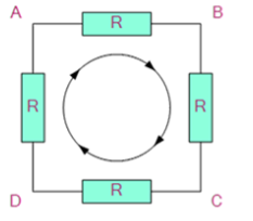
Kirchoff’s law for circuit rules are two equalities that deal with the current and potential difference in the analog circuits model of electrical circuits.
Kirchhoff’s Laws of current and voltage are important to circuit analysis. With these two principles, as well as the equations for individual components (resistor, capacitor, inductor), we have the fundamental tool set required to begin studying circuits.
This essay assumes you already know what a node, distributed node, branch, and loop are.
You should have a pencil and paper ready to go through the sample issues.
Kirchoff’s laws are essential for calculating how circuits will respond. While Ohm’s law may explain the behaviour of a basic resistive network, Kirchoff’s rules can describe the behaviour of a more complex network.
Kirchoff’s Laws
Kirchoff’s laws apply to both electrical and electronic circuit analysis. The first, Kirchoff’s first law, deals with current in a circuit and is also known as Kirchoff’s current law. The second, plainly known as Kirchoff’s second law, deals with voltages within a circuit and is also known as Kirchoff’s voltage law.
The bullet points below provide a general overview of the laws:
Kirchoff’s Current Law
Kirchoff’s First Law (Current Law): This means that the current coming into a node, such as a junction in a circuit, is equal to the current flowing out of it. This is due to charge conservation, which states that charge cannot simply arise or disappear.
In the following diagram, the currents I1 and I2 entering the node are regarded positive in values, while the currents I2 leaving the node are considered negative. This may be stated mathematically as follows:
I1 + I2 – I3 = 0
A Node is a junction or connection of two or more current-carrying pathways such as cables and other components. Parallel circuits can also be analysed using Kirchhoff’s current law.
Kirchoff’s voltage law
Kirchoff’s voltage law (2nd Law) asserts that the total of all voltages from components that produce electrical energy, such as cells or generators, will equal the sum of all voltage drops across the other components in the same loop in any full loop inside a circuit. This rule is a direct result of energy conservation as well as charge conservation.
When you start at any position in the loop and continue in the same way, notice how the voltage declines in all directions, whether positive or negative, and then return to the same spot. It is critical to keep the direction either counterclockwise or clockwise; otherwise, the final voltage value will not be zero. The voltage law may also be used to analyse series circuits.
When analysing either AC or DC circuits using Kirchhoff’s circuit rules, you must be familiar with all of the terminology and concepts that characterise circuit components such as routes, nodes, meshes, and loops.
Vab + Vbc + Vcd + Vda = 0
What exactly are Kirchhoff’s Laws?
Gustav Kirchhoff, a German scientist, published a pair of rules dealing with the conservation of current and energy inside electrical circuits in 1845. Kirchhoff’s Voltage and Current Law is the popular name for these two laws.
Limitations of Kirchhoff’s Laws
Kirchhoff’s circuit rules arise from the lumped-element model, and both are dependent on the model being appropriate to the circuit in issue. The laws do not apply when the model is not relevant.
The current law assumes that the net charge in any wire, junction, or lumped component is constant. This may not be the case when the electric field between circuit components is not minimal, such as when two wires are capacitively connected. This happens in high-frequency alternating current circuits where the impedance matching model is no longer appropriate. In a transmission line, for example, the charge density in the conductor is constantly fluctuating.
Kirchhoff’s Circuit Laws Application.
These two rules allow the Currents and Voltages in a circuit to be determined, i.e. the circuit is said to be “Analyzed,” and the fundamental technique for employing Kirchhoff’s Circuit Laws is as follows:
- Assume that all voltages and resistances are specified. (If not, mark them V1, V2,… R1, R2, and so on.)
- Assigns a current (clockwise or anticlockwise) to each branch or mesh
- Assign a branch current to each branch. (I1, I2, I3, and so on.)
- For each node, get the Kirchhoff’s first law equations.
- Determine Kirchhoff’s second law equations for each of the circuit’s independent loops.
- As needed, use linear simultaneous equations to obtain the unknown currents.
